How to Drill a Guitar Pedal Enclosure
Drilling an aluminium enclosure is the point in a pedal build where a mistake becomes permanent. A hole in the wrong place can’t be unmade, and no amount of filing gets you back.
Accuracy here is a process, not a skill. Get the hole centres onto the enclosure exactly where the layout puts them, dimple each one so the bit can’t wander, then open the holes up in stages. Do those three things and a cordless drill on a kitchen table will give you clean results.
This guide covers the whole job, and both of the ways a layout gets onto the enclosure: a printed paper template, which costs nothing, and a 3D printed drill jig, which is faster and harder to get wrong. Everything from the centre punch onwards is the same either way. If you’re here for the hole sizes, they’re further down.
What you need
- A spring-loaded centre punch, which matters more than anything else on this list. It fires without you shifting your aim, which a hammer-and-pin punch can’t do. The Starrett 18A is the one I use, and its tip has stayed sharp through a lot of enclosures. It isn’t cheap, so start with a cheap one if you’d rather find out whether you enjoy this first.
- Sharp drill bits. Cobalt high-speed steel (HSS-Co) stays sharp longer in aluminium and cuts cleaner than standard HSS.
- A step drill bit (sometimes called a Unibit), 3 mm to 12 mm.
- Low-tack masking tape.
- Something to hold the enclosure still. A clamp or a vice.
- Safety glasses.
- Either a printed paper template or a drill jig, covered below.
Step 1: Design the layout
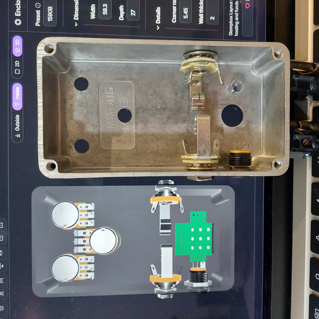
Every hole position is decided on screen, before you touch the enclosure. Use Stompbox Layout to place each one, starting from your enclosure preset (125B, 1590B, 1590BB and the rest) so the outline and the wall positions are already correct.
Place real components rather than plain circles. The editor’s component library carries the actual parts, so a 3PDT footswitch, an Alpha pot or a Switchcraft jack arrives with its own hole size, its footprint and the space its body needs behind the panel. It will warn you when two parts are going to collide inside the enclosure, which is hard to spot on a flat drawing.
Check the 3D preview before you commit. Nudge things until the spacing looks right, the knobs have room for fingers, and nothing fouls the PCB. A problem you find here costs nothing; the same problem found halfway through drilling costs you the enclosure.
Step 2: Get the centres onto the enclosure
This is the step that decides whether the pedal comes out straight, and it’s the only part of the job with two genuinely different answers.
- A printed paper template costs nothing and needs no equipment beyond a printer, scissors and tape. It’s the right answer for your first build, and for anyone drilling one enclosure.
- A 3D printed drill jig is a part that sits on the enclosure with a hole over every centre. It fits snugly and stays put, so there’s nothing to align and nothing to tape down. It’s worth it when you’re drilling the same layout more than once, or when you want the sides to line up without thinking about it.
Both are covered below. Pick one, then rejoin at the drilling.
Route A: The paper template
Print it at 100% scale
Export the layout as a PDF, then print it with scaling switched off. Don’t let your printer “fit to page”. Every PDF the editor exports carries a printed ruler for exactly this reason: measure it before you cut anything. If the ruler is right, every hole on the sheet is right.
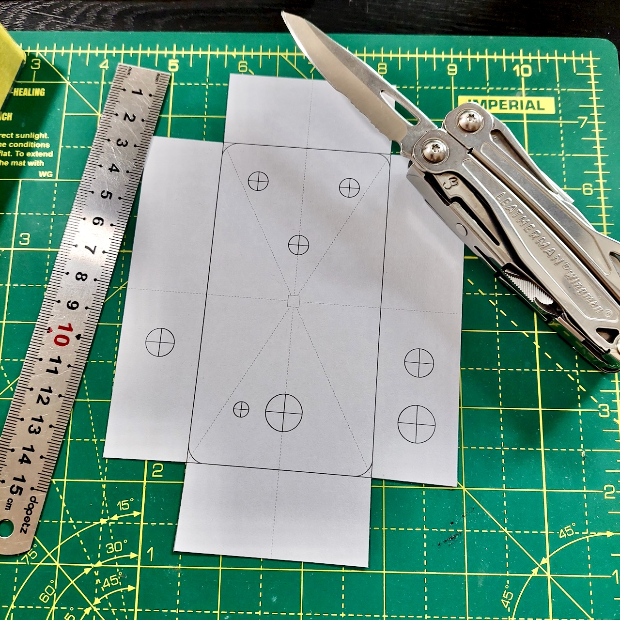
The sheet has the top face with a crosshair on every hole centre, and fold-down panels for the side walls so the jack and DC positions come with it.
Cut it out
Cut around the outer edge with scissors or a craft knife, and leave the side panels attached. You fold those down later.
Tape the enclosure
Cover the top and the sides in low-tack masking tape. The tape gives the paper something to grip, protects the finish while you work, and takes a pencil mark clearly. Ordinary painter’s tape is fine.
Mark the centre of the top face
The template locates off the centre of the enclosure, so you need that point marked accurately. Measure the width and the length, halve each, and draw a short cross with a set square.
Align the template
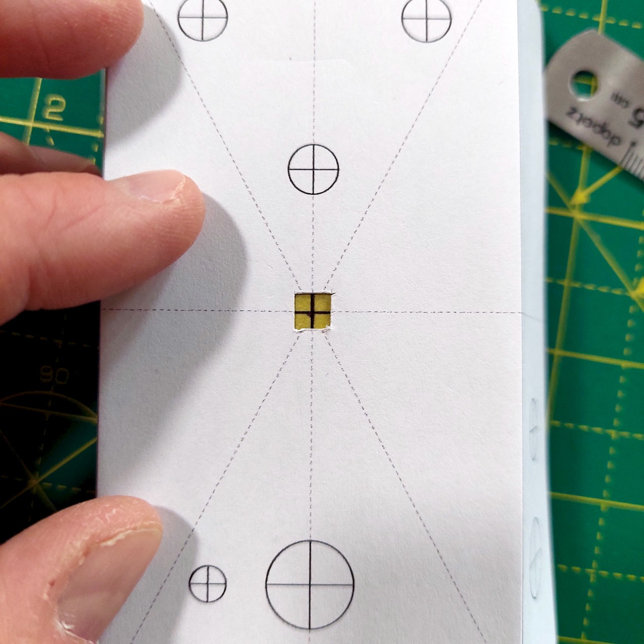
The sheet has a small square in the middle with alignment lines running out of it. Cut that square out, drop the template onto the enclosure, and line the printed lines up with the cross you just drew.
Take your time. This one alignment sets the accuracy of every hole on the pedal, and it’s the step people rush.
Fold the panels down and tape it
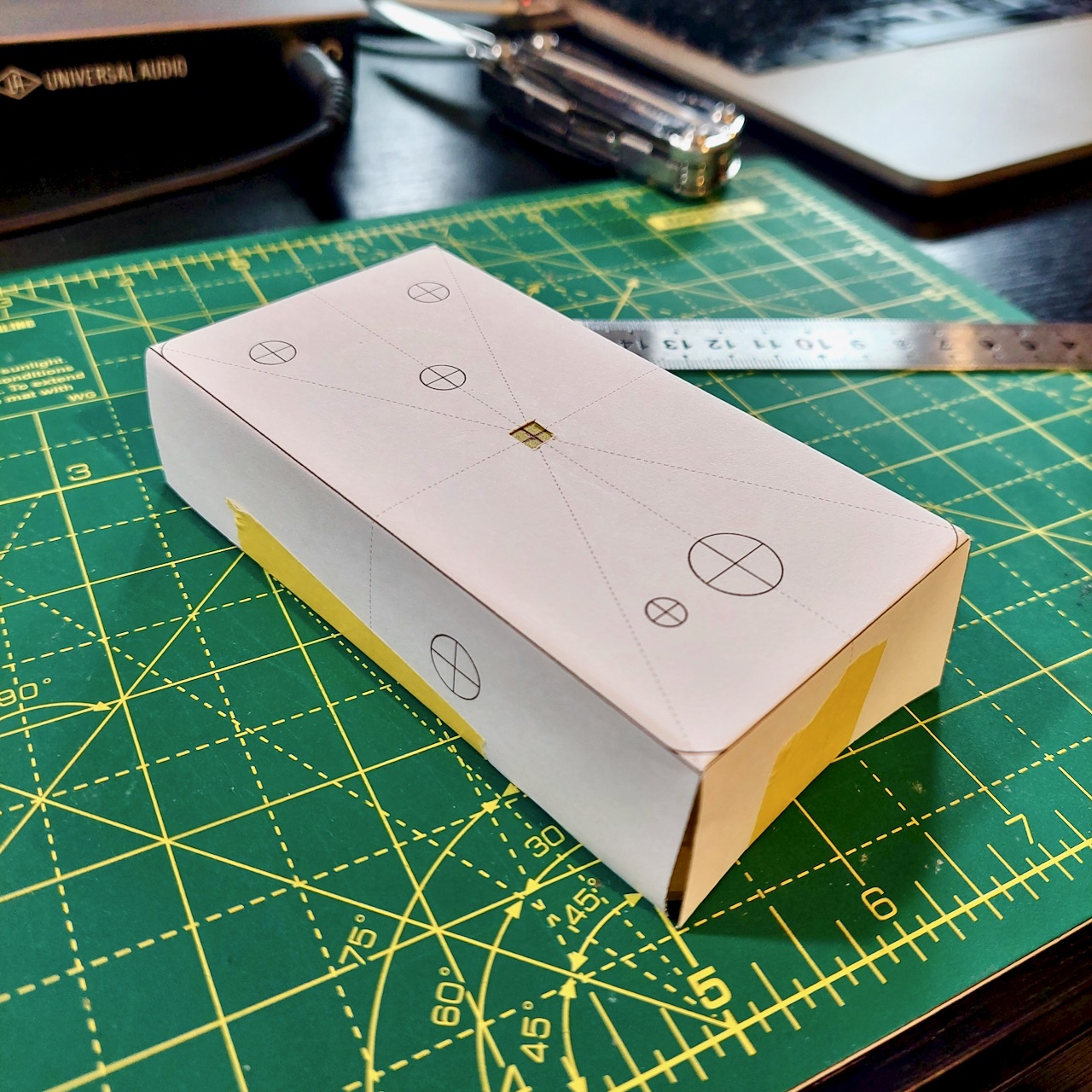
Fold the side panels over the walls and tape them firmly. The wrap is what stops the sheet creeping while you lean on the punch. A couple of strips a side is enough.
Punch every centre
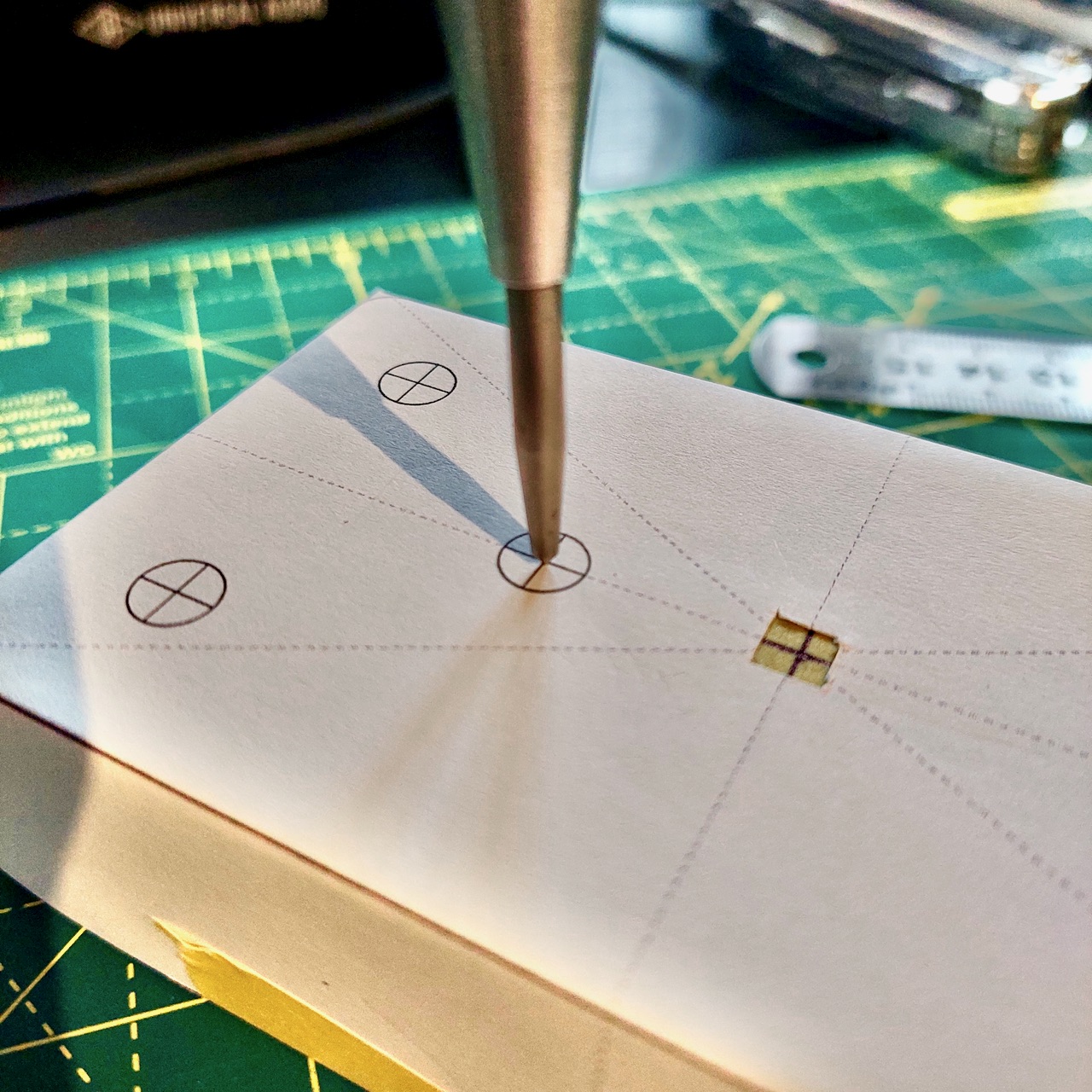
Work through the crosshairs one at a time. For each one:
- Rest the punch tip lightly in the middle of the crosshair.
- Spin the enclosure slowly, watching the tip. Rotating it makes any offset obvious, because the crosshair swings around a tip that isn’t centred and sits still under one that is. It checks both axes at once, which your eye can’t do looking straight down.
- When the crosshair stops moving, press until the punch fires.
- Check the dent. A second strike gives the drill bit a deeper seat, and it costs you nothing.
Punch every hole before you pick up a drill, and check them all against the template while the paper is still on. A dent in the wrong place is a two minute problem now and a scrap enclosure in ten minutes.
Route B: The 3D printed drill jig
A jig is printed to fit your enclosure. It drops on, grips, and puts each centre exactly where the layout put it. Nothing to tape down, nothing to slip, and no centre to find, so the whole of Route A above collapses into one step.
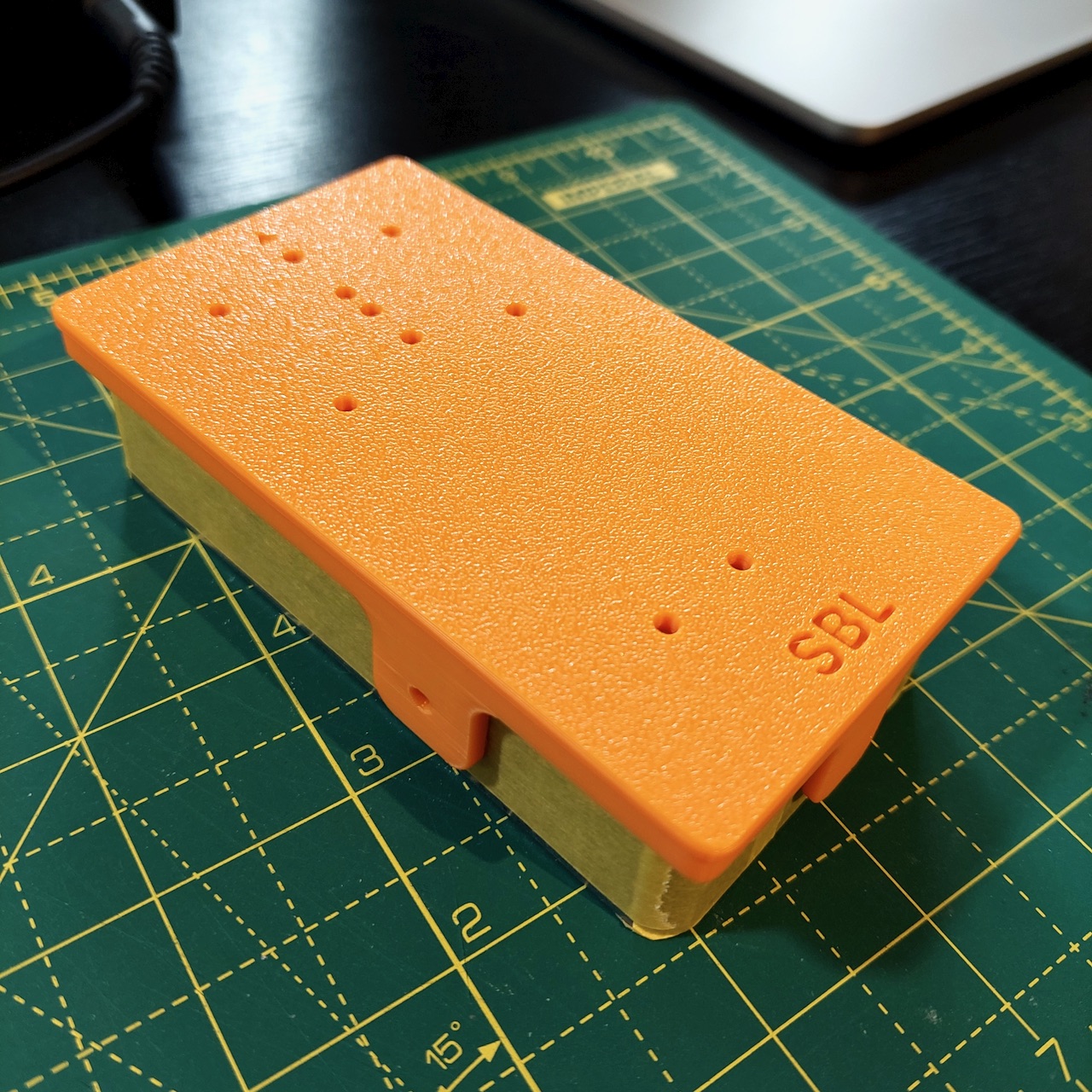
To use one:
- Seat the jig on the enclosure. It fits snugly, so it should stay put on its own while you punch.
- Punch the holes your build uses, including the ones in the side walls. A jig made from your own layout has only your holes on it. A pack jig covers several builds, so its guide shows which ones to punch.
- Lift the jig off and check the dimples.
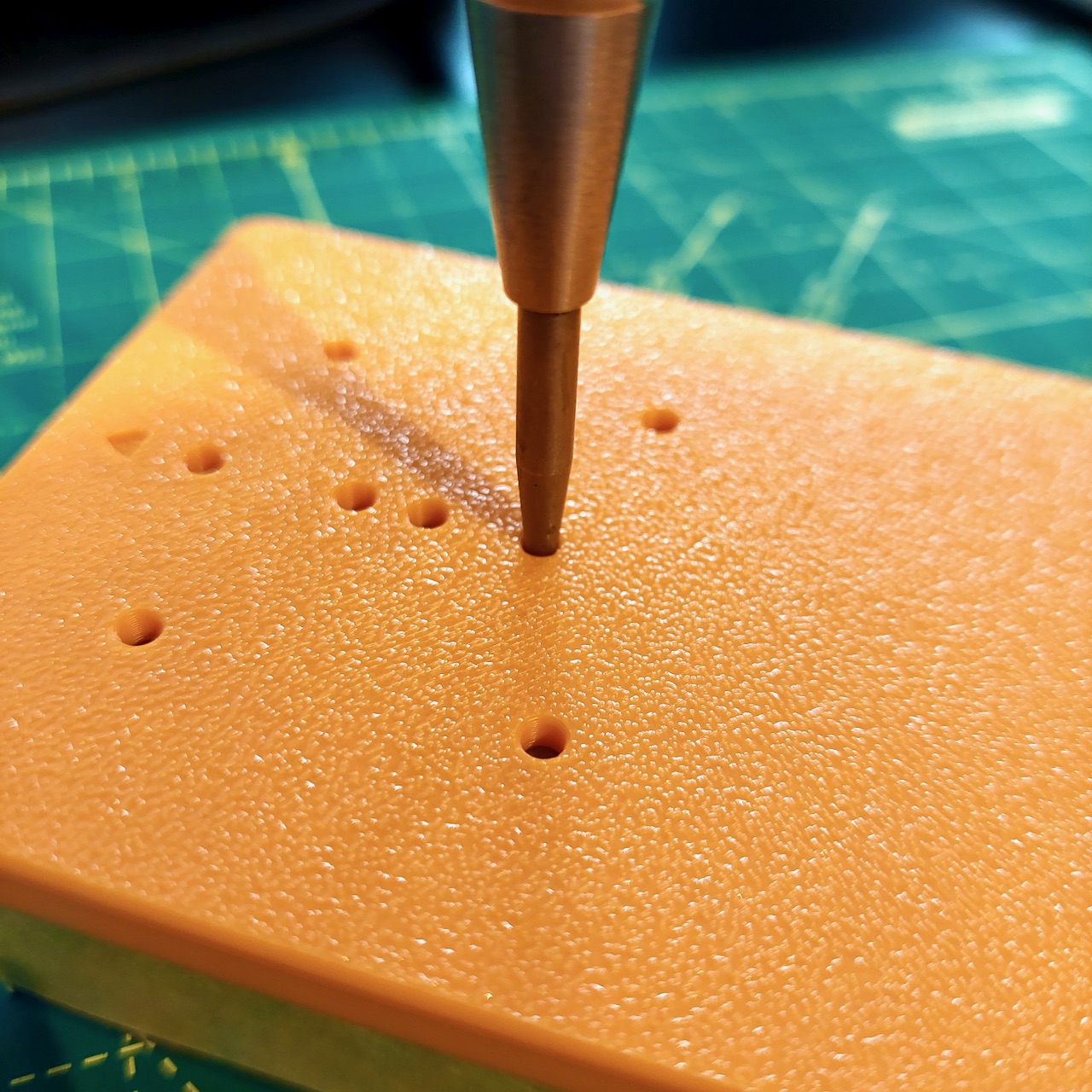
Punch through the jig. Never drill through it. A twist bit self-feeds in plastic and reams the hole oversize as it goes, so the jig gets less accurate with every hole you cut and you can’t see it happening. The jig exists to put a dimple in the right place. Take it off before you drill, and drill into that dimple exactly as you would from a paper template.
Where to get one
There are three ways, depending on what you’re building and whether you own a 3D printer.
- A ready-made pack, if you’re building a board from a maker we cover. A pack is one or two jigs that between them cover most of that maker’s builds in a given enclosure, from a single download. See the drill jig packs.
- Generated from your own layout, for anything else. The editor builds a jig for the exact enclosure and the exact holes in your project, and exports it as an STL you print yourself. It’s $29 once, and every project you make after that can export one. See the drill jig.
- Ready printed, if you have no 3D printer. We print and post them within the UK only. The jig pages have the prices, and how to ask if you’re somewhere else.
A jig isn’t the answer for one pedal, and the paper template genuinely works. It pays off on the second identical build, on side holes, and on anything with enough holes that aligning a sheet stops being fun.
Before you drill
Clamp the enclosure. Use a vice with soft jaws, or clamp it to the bench. A loose one spun by a grabbing drill bit is sharp and moving fast, and a bit that catches on breakthrough will try.
Safety glasses, and no gloves. Aluminium swarf comes off hot, sharp and airborne. Gloves near a rotating bit are worse than bare hands, because a glove that catches takes your hand with it.
Step 3: Drill the pilot holes
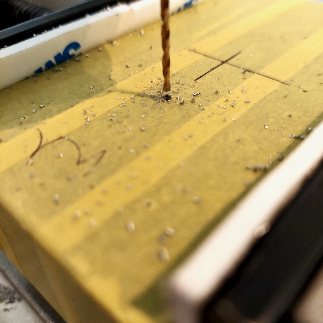
Pilot holes aren’t optional. Going straight in with a large bit is the fastest way to ruin an enclosure: the bit wanders off the dimple, the hole ends up oversize, and it’s oversize in a direction you didn’t choose.
Getting the hole square
What matters is that the pilot goes in perpendicular to the face. A hole that starts crooked stays crooked all the way up to final size, and no amount of care at the step drill will straighten it. In order of what they cost:
- A pillar drill is the right tool, and holds the bit square without you thinking about it.
- A rotary tool in a drill stand gets you most of the way for a fraction of the money. There’s more play in it than a proper drill press and you can feel it, but it holds the tool square, which is the part that matters. A Dremel 220 Workstation holds the tool vertically and gives you a lever-action plunge, and a Multi Chuck lets it take standard round-shank bits instead of collets.
- A cordless drill, carefully, which is what most people start with and it does work. Get your eye level with the face, check square from two directions before you start, and let the dimple do the locating.
Technique
- Start with a 1.5 mm pilot, then open to 2.5 mm or 3 mm before the step bit.
- Keep the speed low. High RPM in aluminium generates heat, and hot aluminium welds itself to the cutting edge and blunts the bit.
- Take small bites. Plunge gently, back off to clear the swarf, plunge again. Don’t lean on it to get through in one go.
- A drop of cutting fluid helps, and plain WD-40 works well enough on aluminium if you have nothing else.
- Ease off on breakthrough. The last fraction of a millimetre is where a bit grabs, snatches the enclosure and tears the hole.
Step 4: Step drill to final size
With a clean pilot in every hole, switch to the step bit. It follows the pilot and widens the hole one increment at a time, so no single step takes enough metal to grab.
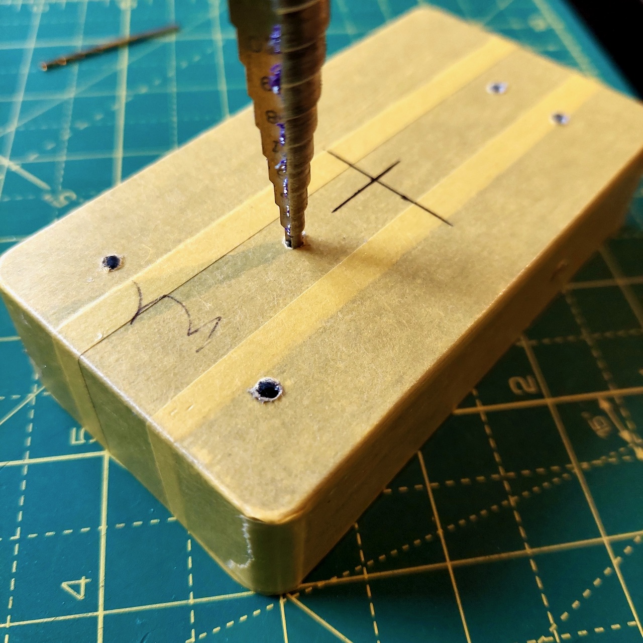
Go slowly, check the size after each step, and stop the moment you reach the diameter you want. It’s easy to take one step too many while you’re in a rhythm.
Slightly over is usually fine. A pot, a jack, a footswitch or a DC socket is held by a nut with a washer under it, and that covers a hole a few tenths oversize without anyone knowing. Where a hole does have to be right, a hand reamer opens it a little at a time, so you can creep up on the diameter and stop when the part just fits instead of committing to the next step on the bit.
Pedal enclosure hole sizes
A step bit running 3 mm to 12 mm covers effectively every common pedal part. These are the sizes most builders drill:
| Component | Hole | Notes |
|---|---|---|
| 3 mm LED | 3 mm | Straight through the face, no holder |
| 5 mm LED | 5 mm | 8 mm with a bezel holder |
| 16 mm and 9 mm potentiometers | 7 mm | Alpha and most clones use a 7 mm bushing |
| Mini toggle switch | 6 mm | SPDT and DPDT, on-on and on-off-on |
| 3PDT footswitch | 12 mm | The nut is about 19 mm across, so leave room around it |
| Quarter-inch jack | 9.5 mm | 3/8 inch exactly. A 1 mm step bit lands on 10 mm, which is fine |
| Cliff-style jack | 12 mm | Check yours, the range here is wide |
| 2.1 mm DC power jack | 12 mm | Panel-mount barrel type |
Treat that as a starting point and not gospel. Parts vary between suppliers, and the only number that’s certainly right is the one off your own calipers. Where a part is in the editor’s component library its hole size comes with it, so the drill template and the jig are already sized for the part you picked.
Drilling the side faces
Jacks and power sockets go through the walls, and the walls are where this gets harder. They’re thinner than the top, they’re usually tapered rather than square to the world, and there’s nothing to rest the drill against.
- Clamp the enclosure on its side so the face you’re drilling is horizontal. Trying to drill sideways into an enclosure standing upright is how side holes end up at an angle.
- Check your punch marks on the walls before you drill. A thin, curved wall gives the bit more excuse to skate, so a shallow dimple is worth redoing here even where it would do on the top.
- Go slower on breakthrough than you did on the top face. There’s much less metal to grab through.
- Check the inside for a burr before you fit anything. A burr on a jack hole holds the washer off the wall and the nut will never sit flat.
Step 5: Deburr and check
Peel the masking tape off first. Every hole comes out with a raised lip on both faces, and the tape hides it. Take the lip off with a countersink bit turned by hand, a file, the back edge of a larger drill bit, or a deburring tool. A couple of turns is enough. You’re knocking the edge off, not cutting a chamfer.
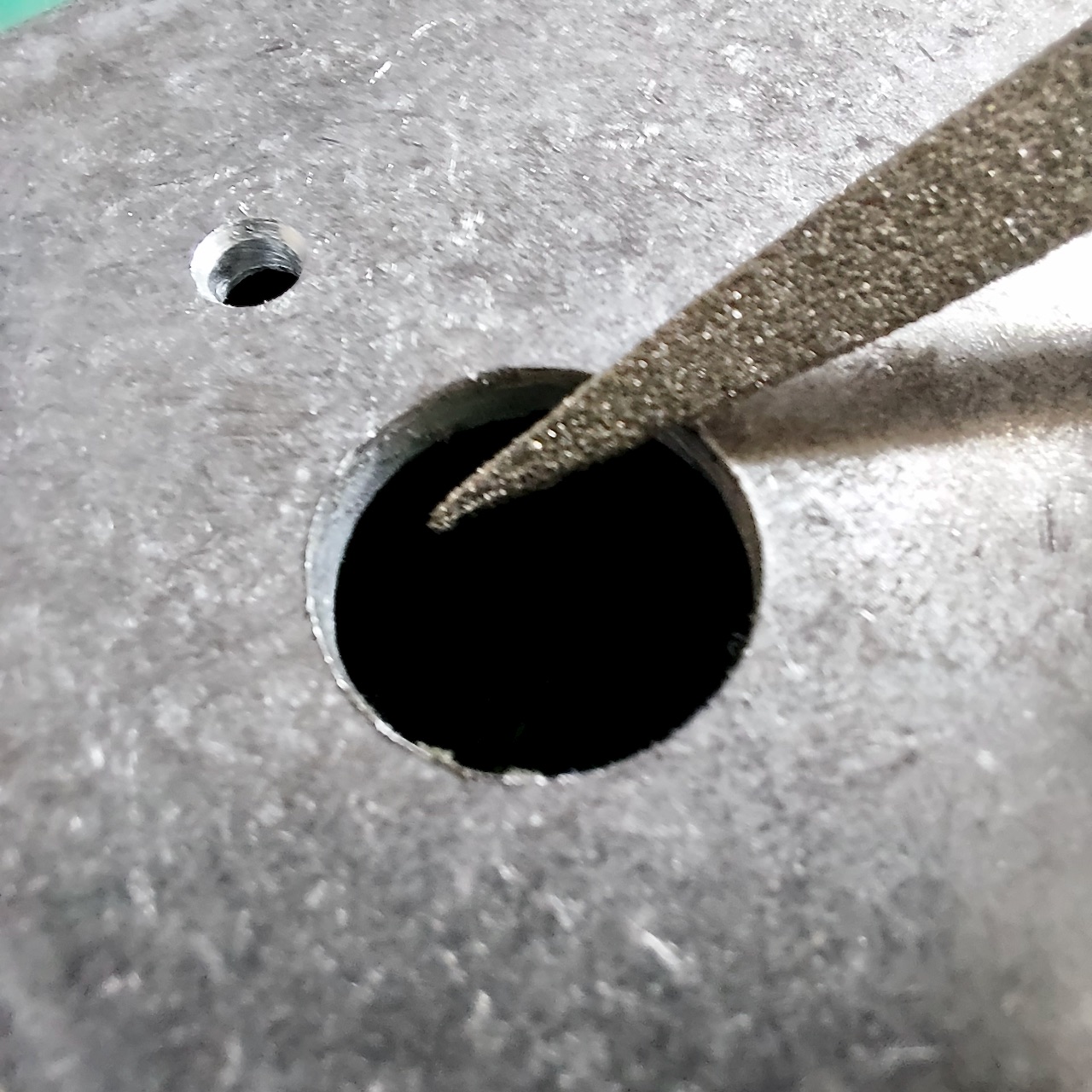
Then dry fit everything before you paint or wire, while a problem is still cheap to fix. Components in, nuts on, lid closed.
When it goes wrong
It will, eventually, so it’s worth knowing which mistakes are recoverable.
- A hole off position, oversize, or gone oval. All three have the same fix: a larger flat washer under the nut, sized to cover the worst of it. On a pot or a jack it disappears entirely, and a knob with a wider skirt buys you more again.
- A hole in completely the wrong place. That’s a new enclosure, and the old one is worth keeping to practise on.
The short version
- Design the layout, with real components, and check it in 3D.
- Get the centres onto the enclosure: a paper template printed at 100%, or a drill jig.
- Centre punch every hole. Spin the enclosure to verify each one.
- Clamp the enclosure. Glasses on, gloves off.
- Pilot at 1.5 mm, then 2.5 mm to 3 mm, square to the face, low speed.
- Step drill to size, checking the fit after each step.
- Deburr both faces and dry fit everything.
The two steps that decide the result are the alignment and the punch. The drilling itself isn’t hard, but it can’t recover a centre that was dimpled in the wrong place, so that’s where the care is worth spending.
Not starting from a blank enclosure? Browse the drill template collections for ready-made layouts you can open and adapt, or pick your enclosure and start from its dimensions.