B-Side Fuzz Drill Template
PedalPCB · 125B
Template details
- Circuit
- B-Side Fuzz
- Vendor
- PedalPCB
- Enclosure
- Hammond 125B
- Dimensions
- 63.6 × 119.3 × 35.8 mm
- Layout
- 125B 4-Knob (Type 1)
- Category
- Fuzz
Export formats
- PDF: print at 1:1 scale
- SVG: vector graphic
About this drill template
Drill template for the PedalPCB B-Side Fuzz, sized for a Hammond 125B enclosure (63.6 × 119.3 × 35.8 mm). The pre-positioned holes match the PCB's pot footprint exactly, with the footswitch centred below the 4-knob layout. Print at 1:1 scale, tape to the enclosure face, centre-punch, and drill. PCB and parts not included.
PedalPCB description: “The B-Side Fuzz was inspired by the Mid-Fi Electronics Demo Tape Fuzz, a pedal designed to emulate the distortion created by a 4-track/mixer/mic pre.”
PedalPCB says the B-Side Fuzz was inspired by the Mid-Fi Electronics Demo Tape Fuzz, a pedal built to emulate a 4-track recorder overloading a mic pre. Bass and Treble shape the mangled signal while Trim sets the gain going in.
Lo-fi, gated fuzz with a sputtery, tape-overload character rather than a smooth sustain.
Build notes
Four-knob layouts are dense but manageable: the pots are spaced wide enough to grab individually, with the footswitch centred below.
The Hammond 125B is one of the most common DIY pedal enclosures: a touch larger than a 1590B, slightly smaller than a 1590BB, with room for almost any single-effect PCB plus 9V supply.
Vendor specs: Designed for a 125B enclosure with top-mounted jacks
Controls
- Volume: Control the amount of output signal
- Bass: Adjusts the level of bass frequencies
- Treble: Adjusts the level of treble frequencies
- Trim: Control the amount of signal gain
Drill measurements
Hole centres for the 125B 4-Knob (Type 1) layout. X runs left to right from the centre of the face being drilled. On the enclosure face, Y is measured from the centre, positive towards the top. For holes on a side, Y is the distance down the wall, measured from the face edge. Export the PDF for a 1:1 printable version with a scale check.
| Hole | Face | X (mm) | Y (mm) | Diameter |
|---|---|---|---|---|
| Pot | Enclosure face | -16.5 | 38.1 | 7 mm (0.28 in) |
| Pot | Enclosure face | 16.5 | 38.1 | 7 mm (0.28 in) |
| LED | Enclosure face | 0 | 25.4 | 6.4 mm (0.25 in) |
| Pot | Enclosure face | -16.5 | 12.7 | 7 mm (0.28 in) |
| Pot | Enclosure face | 16.5 | 12.7 | 7 mm (0.28 in) |
| Footswitch | Enclosure face | 0 | -45 | 12 mm (0.47 in) |
| DC Jack | Top side | 0 | 14.2 | 8 mm (0.31 in) |
| Jack | Top side | -15.2 | 24.3 | 9.5 mm (0.37 in) |
| Jack | Top side | 15.3 | 24.3 | 9.5 mm (0.37 in) |
Never drilled one before? How to drill a pedal enclosure walks you through the entire process, from punching the centres to the final step drill size.
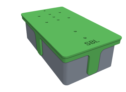
Jig A covers 125B 4-Knob (Type 1)
Drop it over the enclosure, punch a mark through the holes this build uses, then lift it off and drill. It wraps onto the sides too, so the jacks and DC socket are covered.
See the jig pack, $12 →